ELECTRICAL INTEGRATION / ENGINEERING GUIDE
Load Pin Output, Wiring & Readout Selection
The same mechanical pin envelope can be paired with different signal paths. Choose the destination first: a bridge conditioner, a PLC analog input, a digital network or an operator display. Then check the available pin-head space, power and the complete connection diagram.
LoadPinSensor.com engineering desk · Reviewed 29 October 2026
Apply this guide to my joint ↗WHAT TO PREPARE
A bridge output needs excitation and a defined conditioner
For an mV/V bridge request, state the intended conditioner, excitation, bridge impedance, sensitivity range and cable length. Four-wire and six-wire arrangements need the instrument’s actual wiring instructions; wire colors and connector pin numbers are not universal. Keep the approved pinout with the pin identity.
- Identify excitation and signal pairs, plus sense connections where used.
- State shielding/grounding and connector termination requirements for the installation.
- Include conditioner input range, sampling and filtering needs in the system review.
An amplified output needs a complete power and scaling brief
For 4–20 mA or 0–10 V, identify the supply, input topology at the receiving instrument and the load range mapped to the output. Internal electronics must also fit the pin head and environment. The configurator includes the amplifier request automatically when an internal analog or digital signal is selected; a formal quote confirms the feasible package.
- Confirm two/three/four-wire topology on the actual proposed device rather than infer it from “4–20 mA”.
- For RS485 or CAN, state protocol, address, baud rate, data mapping and channel count.
- Request the configured scaling and connector schedule as part of the supply documents.
A readout kit is a list of compatible parts
Specify the sensor, conditioner or transmitter, receiver/display, leads, connectors, power/battery arrangement and commissioning/calibration scope together. Existing proprietary radio receivers may not pair with another transmitter. A NMEA 2000 request needs an identified interface or gateway and a confirmed integration scope.
- State the actual phone, receiver or display model you want to use.
- Define update rate and radio layout independently from the pin’s load range.
- For X/Y measurement, agree how both signed channels and the vector result reach the destination.
| Item / condition | Information to confirm | Decision boundary |
|---|---|---|
| mV/V bridge | External bridge conditioner / indicator | Excitation, impedance, sensitivity, cable and input range |
| Internal analog | PLC or analog indicator | Supply, current/voltage topology, scaling and load limits |
| Digital | PLC / data acquisition network | Protocol, bus settings, channel mapping and pinout |
| Wireless / handheld | Operator receiver or display | Transmitter/receiver match, power, update rate and antenna path |
electrical integration: questions to resolve
Can I wire two pins in parallel to get an average?
Do not assume that an arbitrary pin pair and conditioner can be combined this way. Identify the acquisition method, bridge loading and calibration requirement for each channel.
Are colors or pin numbers shown on this page universal?
No universal pinout is supplied. Use the released connector schedule and the manuals for the selected electronics.
Original technical references
- Mantracourt: bridge measurement and connection manual
- Mantracourt: digital conditioner interfaces and protocol documentation
References describe their manufacturers’ products and methods. They do not establish MT-LPS compatibility, certification or performance. Our diagrams and worked briefs are illustrative; configuration-specific documents govern supply and installation.
Continue your engineering brief
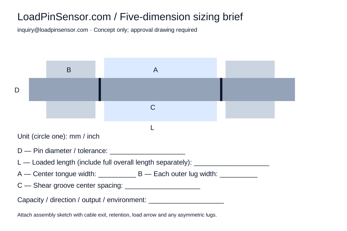
THE FIVE-DIMENSION BRIEF
Your existing pin is the starting point.
Measure D / L / A / B / C or attach a sketch. We review the joint, load cases and interfaces before releasing a drawing or quotation.
- D
- Pin diameter and fit
- L
- Overall loaded length
- A
- Center loading tongue width
- B
- Each outer clevis lug width
- C
- Shear-groove center spacing
L describes the loaded span here. Include the overall end-to-end length, asymmetric lugs, spacers and retention details in your drawing or notes. Five values start the review; they do not fully define a production pin.
Download sizing sheet ↓