mV/V
Bridge + conditioner
Specify excitation, bridge impedance, sensitivity, cable length, shield grounding and calibration access. External electronics keep the pin head compact.
FROM PIN TO CONTROL SYSTEM
Define what the pin must connect to, then choose the signal path. Diameter, head space, power, cable length and environment determine the practical electronics package.
mV/V
Specify excitation, bridge impedance, sensitivity, cable length, shield grounding and calibration access. External electronics keep the pin head compact.
4–20 mA / 0–10 V
Confirm power supply, two/three/four-wire topology, output scaling and available pin-head volume. RS485 / CANopen requests need protocol details.
Bluetooth / handheld
Confirm above-water antenna placement, update rate, line-of-sight range requirement, battery access and the intended phone or receiver.
For X/Y pins, define each channel's direction, full-scale range and output. Combine the readings using magnitude √(Fx² + Fy²) and angle atan2(Fy,Fx). Cross-axis sensitivity and installed-joint calibration form part of the acceptance plan.
NMEA 2000 instrument integration is assessed through a compatible interface or gateway. Device compatibility, data messages, certification requirements and system testing are confirmed before quoting. An IP68 pin alone does not establish wireless or network compatibility.
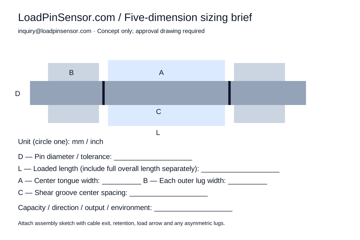
THE FIVE-DIMENSION BRIEF
Measure D / L / A / B / C or attach a sketch. We review the joint, load cases and interfaces before releasing a drawing or quotation.
L describes the loaded span here. Include the overall end-to-end length, asymmetric lugs, spacers and retention details in your drawing or notes. Five values start the review; they do not fully define a production pin.
Download sizing sheet ↓