JOINT GEOMETRY / ENGINEERING GUIDE
Load Pin Installation & Anti-Rotation Guide
An installation review starts with the assembled load path. The following checklist helps a machine owner and installer prepare a usable drawing brief; the configuration-specific installation drawing governs the actual work.
LoadPinSensor.com engineering desk · Reviewed 29 October 2026
Apply this guide to my joint ↗WHAT TO PREPARE
Locate where each member actually contacts the pin
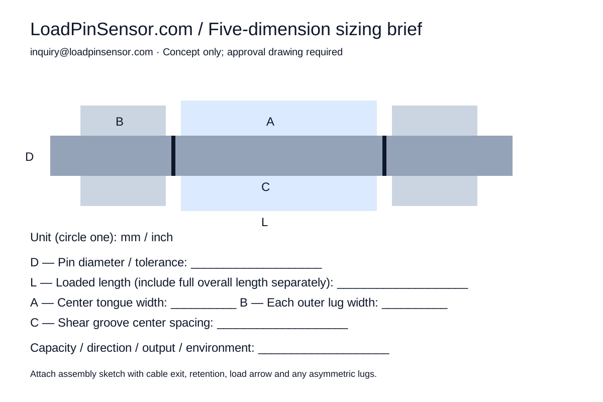
Record the center tongue, both outer lugs, sleeves, bushings and spacers. Use D for the pin diameter, A for the center contact width, B for each outer lug width and C for the shear-plane spacing. In this site’s brief, L is the loaded span; show the full end-to-end length separately. If the two lugs differ, write B-left and B-right on a sketch rather than averaging them.
- Mark the load arrow and the angular sensing datum on the same assembly view.
- Include the bore fit and concentricity/alignment observations; do not assume diameter alone defines the fit.
- Show any lubrication channel, bearing shoulder or extraction feature that occupies the pin section.
Separate angular location from axial retention
A keeper slot and plate can establish angular position. A cotter, nut or retaining ring can prevent axial escape, but should not be assumed to control the sensing direction. Identify the intended function of every retaining feature and the available mounting space. This is also where a no-structural-change replacement must be checked: plate fasteners and cable clearance may need work even when the sensing pin uses the existing bore.
- Show the keeper plate mounting and access to its fasteners.
- Check the complete motion envelope of an articulating clevis.
- Keep the cable clear of the moving eye and specify strain relief and service access.
Record the installed measurement check
After the assembly and electrical connection have been accepted by the responsible installer, the measurement needs checking against a known applied load and direction under the agreed procedure. Record the fixture arrangement, zero, scaling and any installation-dependent difference. A factory calibration on a different contact distribution may not by itself close the installed-system check.
- Use the released drawing and model-specific instructions for mounting and connection.
- Agree the check method and acceptance limits before commissioning.
- Keep the installation drawing, pin identity and calibration record together.
| Item / condition | Information to confirm | Decision boundary |
|---|---|---|
| Interference or misalignment | Pin cannot be inserted as intended | Review bores, bushings and fits against the drawing; do not force an unreviewed fit |
| Pin can rotate | Sensing axis changes relative to the load | Review keeper datum and angular retention |
| Unclear load contact | Calibration fixture differs from the joint | Document contact widths and agree an installed check |
joint geometry: questions to resolve
Is the online dimension check an installation approval?
No. It screens basic numerical consistency. It cannot assess stress, fatigue, fit or the assembled load path.
Which length should be entered as L?
Enter the loaded span used in the five-dimension brief and identify the full overall length separately in fit notes or a drawing.
Original technical references
References describe their manufacturers’ products and methods. They do not establish MT-LPS compatibility, certification or performance. Our diagrams and worked briefs are illustrative; configuration-specific documents govern supply and installation.
Continue your engineering brief
THE FIVE-DIMENSION BRIEF
Your existing pin is the starting point.
Measure D / L / A / B / C or attach a sketch. We review the joint, load cases and interfaces before releasing a drawing or quotation.
- D
- Pin diameter and fit
- L
- Overall loaded length
- A
- Center loading tongue width
- B
- Each outer clevis lug width
- C
- Shear-groove center spacing
L describes the loaded span here. Include the overall end-to-end length, asymmetric lugs, spacers and retention details in your drawing or notes. Five values start the review; they do not fully define a production pin.
Download sizing sheet ↓