MEASUREMENT ACCEPTANCE / ENGINEERING GUIDE
Load Pin Calibration & Test-Scope Guide
A useful calibration request identifies what will be loaded, in which direction and through which supports. It also states what evidence the receiving engineer needs. This guide defines a request framework; it is not a certificate or a claim of accredited laboratory capability.
LoadPinSensor.com engineering desk · Reviewed 29 October 2026
Apply this guide to my joint ↗WHAT TO PREPARE
Match the loading arrangement to the measurement task
Supply a support/contact sketch with the rated direction, minimum useful load, full-scale load and expected peaks. Ask for the calibration procedure to identify its loading fixture and contact distribution. When the installed joint differs from the bench fixture, agree how an in-place check or system calibration will be used.
- Separate sensor-only calibration from pin-plus-conditioner or complete readout-system calibration.
- State loading/unloading points, repetitions and required combined-error evaluation in the test specification.
- Identify temperature conditions, zero treatment and whether cable/conditioner changes are included.
For X/Y pins, document axes and correction together
A dual-axis brief needs signed X and Y directions, channel ranges, output scaling and a method for evaluating cross-axis response. Vector magnitude and angle must use the same axis convention as the calibration record. A radial magnitude alone can conceal the sign or direction of a channel error.
- Request a channel identity and angular datum on the approval drawing.
- Define whether a crosstalk correction matrix is required and where it is applied.
- Check software calculations using known signed input examples before reading hardware values.
Keep calibration, proof and environmental tests distinct
Calibration describes the measurement response under a specified procedure. A proof-load test addresses an agreed load exposure, while an immersion/pressure test addresses a defined environmental condition. None should be substituted for another in the quote or report. Exact limits and pass criteria must be agreed for the actual pin and assembly.
- List each requested test and its acceptance criteria separately.
- Request pin identity, drawing revision, fixture/method and instrument references in the records.
- Specify whether a third-party or accredited service is required; availability and scope need written confirmation.
| Item / condition | Information to confirm | Decision boundary |
|---|---|---|
| Calibration record | Points, direction, fixture, zero/span and channel scaling | Provides the measurement basis for the stated setup |
| Proof-load record | Load, duration, configuration and acceptance method | Not a replacement for calibration or an assembly WLL declaration |
| Environmental record | Depth/pressure, time, temperature, cycles and connector state | Applies to the tested assembly and conditions |
measurement acceptance: questions to resolve
Can I use a factory calibration factor after changing supports?
Describe the change and agree an installed check. Contact distribution and orientation can change the measurement response.
Is a certificate included with every quoted option?
The written quotation must identify which calibration, proof or third-party documents are included. No certificate scope is assumed from a photo or series name.
Original technical references
- Strainsert: troubleshooting load readings and scaling
- Strainsert: bi-axial calibration application note
References describe their manufacturers’ products and methods. They do not establish MT-LPS compatibility, certification or performance. Our diagrams and worked briefs are illustrative; configuration-specific documents govern supply and installation.
Continue your engineering brief
THE FIVE-DIMENSION BRIEF
Your existing pin is the starting point.
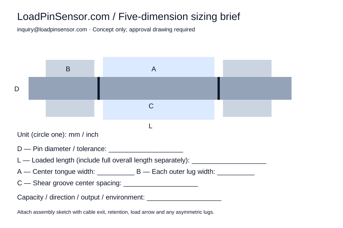
Measure D / L / A / B / C or attach a sketch. We review the joint, load cases and interfaces before releasing a drawing or quotation.
- D
- Pin diameter and fit
- L
- Overall loaded length
- A
- Center loading tongue width
- B
- Each outer clevis lug width
- C
- Shear-groove center spacing
L describes the loaded span here. Include the overall end-to-end length, asymmetric lugs, spacers and retention details in your drawing or notes. Five values start the review; they do not fully define a production pin.
Download sizing sheet ↓