MT-LPS-2D / CUSTOM SHEAR LOAD PINS
Dual-Axis & Subsea IP68 Load Pins
Two orthogonal strain-gauge bridges resolve radial force into X and Y components. Select dual-axis sensing for changing load direction, then specify subsea sealing as a separate environmental requirement.
Ranges describe a custom family envelope. Diameter and capacity are not freely interchangeable; each combination requires mechanical and calibration review.
JOINT-SPECIFIC DECISION POINTS
Check the contact geometry before the capacity.
- Define X/Y reference axes, force envelope, channel scaling and crosstalk targets.
- State water depth, pressure cycles, immersion duration and connector strategy.
- Provide combined load cases, temperatures and fatigue requirements.
Where this pin belongs
Articulating heavy joints · variable-angle sheaves · subsea machinery
What the review returns
X/Y channel and vector calibration plan with stated subsea test conditions.
LOAD-PATH DETAILS
Preserve orientation. Qualify the measurement.
Compute radial magnitude as √(Fx² + Fy²) and direction with atan2(Fy,Fx). This does not measure axial force or torque. Pressure qualification, channel calibration and mechanical proof testing are configuration-specific.
From the blank pin to a calibrated channel
Request material/heat-treatment identification, dimensional inspection of the bore fit and groove locations, insulation checks, and calibration over the agreed load range using representative support geometry. State proof load, combined error, temperature and traceability requirements in the RFQ.
Define acceptance before manufacture.
The quote should identify the approved drawing, rated force direction, overload limits, calibration method, environmental test scope and output scaling. Certificates or lifting approvals are supplied only when explicitly included and verified for the assembly.
Match outputs & readouts ↗THE FIVE-DIMENSION BRIEF
Your existing pin is the starting point.
Measure D / L / A / B / C or attach a sketch. We review the joint, load cases and interfaces before releasing a drawing or quotation.
- D
- Pin diameter and fit
- L
- Overall loaded length
- A
- Center loading tongue width
- B
- Each outer clevis lug width
- C
- Shear-groove center spacing
L describes the loaded span here. Include the overall end-to-end length, asymmetric lugs, spacers and retention details in your drawing or notes. Five values start the review; they do not fully define a production pin.
Download sizing sheet ↓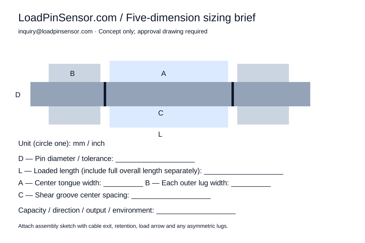
Compare the other load paths.
Clevis pins↗
Hydraulic cylinder eyes · agricultural equipment · automation clevis joints
Winch & sheave↗
Mooring winches · crane sheaves · cable-laying equipment · mining hoists
Marine rigging↗
Yacht rig tuning · forestay and backstay tension · marine towing measurements
Dual-axis & subsea↗
Articulating heavy joints · variable-angle sheaves · subsea machinery
Lifting shackles↗
Suspended-load monitoring · rigging test equipment · stage truss monitoring