GROUND TEST & JOINT LOADS / ENGINEERING GUIDE
Load Pins for Aerospace Ground Tests & Heavy Joints
Ground-test actuators and heavy articulating joints can carry load through clevises, pivots and pinned links. An internally gauged pin can be evaluated at that load path when the structural and measurement requirements are defined together. This page describes engineering tasks, not an approved aerospace component or a customer qualification claim.
LoadPinSensor.com engineering desk · Reviewed 29 October 2026
Apply this guide to my joint ↗WHAT TO PREPARE
Start from the clevis load cases across the full motion
Provide the joint drawing, articulation limits, contact/bushing details and the expected load history. Separate the nominal radial force from shock, reversals, off-axis loads and any axial or bending components. A dimensional replacement must be reviewed against these combined cases before measurement range is assigned.
- Identify the ground-test rig or machinery joint and its responsible design/acceptance owner.
- Send the actuator stroke or joint-angle envelope together with cable clearance.
- State the number of cycles, loading rate, operating temperature and overload exposures.
Choose single-axis or X/Y from the direction information needed
For a fixed radial direction, a single-axis review may be appropriate. When the resultant changes relative to the pin, X/Y channels can support radial magnitude and direction calculations. The coordinate datum must be tied to the joint drawing, and the acquisition system must preserve channel signs and timing.
- Define the axis convention and the required force components, not just a total-load display.
- State sample/update needs and the acquisition hardware or protocol.
- Do not infer measurement of axial force, torque or all six load components from a dual-axis radial pin.
Agree the test article and the documentation boundary
A prototype pin, a calibrated measuring assembly and a released flight article are different supply scopes. Identify the intended use explicitly. For a ground-test or heavy machinery program, define the drawing revision, test fixture, inspection records, calibration plan and review/approval milestones needed for that project.
- Specify material records, dimensional inspection and serial identity as required by the program.
- Separate proof, fatigue and measurement calibration requests with their own acceptance methods.
- Include design effort, prototype quantity and test-document requirements in the quote brief.
| Item / condition | Information to confirm | Decision boundary |
|---|---|---|
| Actuator clevis ground test | Existing eye/clevis contact and known force direction | CLV family review with fixture and fit details |
| Changing-angle heavy joint | Radial direction varies over the motion | 2D family review with signed X/Y channel envelope |
| Rig measurement chain | Pin + acquisition electronics + software | System scaling, channel timing and acceptance record |
ground test & joint loads: questions to resolve
Does this page establish aerospace approval?
No. It describes a ground-test specification route. Qualification, intended use and required program documentation must be explicitly reviewed and agreed.
Should I send a CAD file or only the five dimensions?
Five dimensions can start the conversation. For an articulating joint, include the assembly drawing and motion/load cases so the complete contact and cable envelope can be reviewed.
Original technical references
References describe their manufacturers’ products and methods. They do not establish MT-LPS compatibility, certification or performance. Our diagrams and worked briefs are illustrative; configuration-specific documents govern supply and installation.
Continue your engineering brief
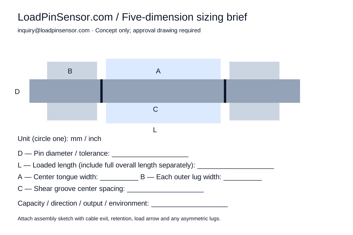
THE FIVE-DIMENSION BRIEF
Your existing pin is the starting point.
Measure D / L / A / B / C or attach a sketch. We review the joint, load cases and interfaces before releasing a drawing or quotation.
- D
- Pin diameter and fit
- L
- Overall loaded length
- A
- Center loading tongue width
- B
- Each outer clevis lug width
- C
- Shear-groove center spacing
L describes the loaded span here. Include the overall end-to-end length, asymmetric lugs, spacers and retention details in your drawing or notes. Five values start the review; they do not fully define a production pin.
Download sizing sheet ↓