MT-LPS / PRODUCT FAMILIES
Load measuring pins, selected by the joint.
Every family measures force inside a cylindrical load-bearing pin. Choose the assembly first, then define diameter, contact widths, sensing direction and capacity.
Clevis pins↗
Hydraulic cylinder eyes · agricultural equipment · automation clevis joints
Winch & sheave↗
Mooring winches · crane sheaves · cable-laying equipment · mining hoists
Marine rigging↗
Yacht rig tuning · forestay and backstay tension · marine towing measurements
Dual-axis & subsea↗
Articulating heavy joints · variable-angle sheaves · subsea machinery
Lifting shackles↗
Suspended-load monitoring · rigging test equipment · stage truss monitoring
| Series | Pin diameter / assembly | Force range | Starting point |
|---|---|---|---|
| MT-LPS-CLV | Ø8–35 mm | 500 N–100 kN | Clevis pins |
| MT-LPS-WCH | Ø35–150 mm | 50–5,000 kN | Winch & sheave |
| MT-LPS-MAR | Ø10–40 mm | 10–300 kN | Marine rigging |
| MT-LPS-2D | Ø20–100 mm | 5–1,000 kN | Dual-axis & subsea |
| MT-LPS-SHK | 1–200 t concept range | 10–2,000 kN | Lifting shackles |
THE FIVE-DIMENSION BRIEF
Your existing pin is the starting point.
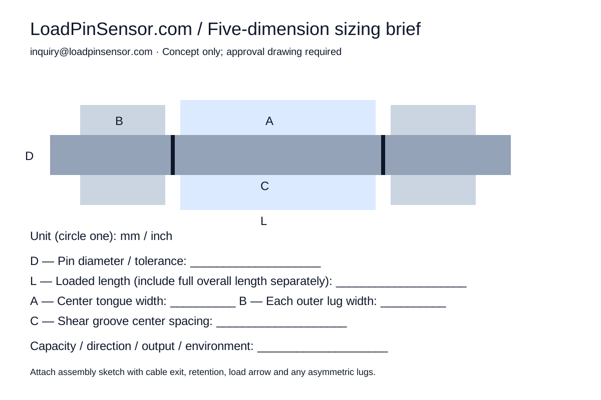
Measure D / L / A / B / C or attach a sketch. We review the joint, load cases and interfaces before releasing a drawing or quotation.
- D
- Pin diameter and fit
- L
- Overall loaded length
- A
- Center loading tongue width
- B
- Each outer clevis lug width
- C
- Shear-groove center spacing
L describes the loaded span here. Include the overall end-to-end length, asymmetric lugs, spacers and retention details in your drawing or notes. Five values start the review; they do not fully define a production pin.
Download sizing sheet ↓