MATERIALS & IMMERSION / ENGINEERING GUIDE
Load Pin Materials, IP68 & Subsea Specification
Marine and subsea requests need a complete environment description. Material grade, heat treatment, surface condition, sealing and cable termination each affect the design review. An exterior reference image cannot establish the steel grade or verified water depth.
LoadPinSensor.com engineering desk · Reviewed 29 October 2026
Apply this guide to my joint ↗WHAT TO PREPARE
Select material against strength and exposure together
17-4PH and 316L are material preferences in the RFQ, not universal replacements for each other. Supply the strength/fatigue duty, seawater or other medium, cleaning chemicals, temperature and contacting metals. The pin section, any heat-treatment condition and the corrosion strategy must then be reviewed for the joint. Neither option should be described as a generic duplex stainless grade.
- State continuous exposure, intermittent splash or immersion separately.
- Identify galvanic contacts, crevices and access for inspection or cleaning.
- Request the material identification and condition to appear in the approved supply documents.
Specify the immersion test as a complete sentence
Instead of writing only IP68, state the required depth or pressure, duration, number of cycles, temperature and connector condition. Identify whether the cable end stays dry, the connector is mated, or the complete assembly is immersed. Subsea pressure exposure and a surface-splash installation are different test requests.
- Mark every cable entry, connector and extension junction in the sealing boundary.
- Specify service pressure separately from any proposed qualification pressure.
- Agree the acceptance method, including electrical insulation and signal checks where required.
Keep the radio path outside the water requirement
A sealed pin can be cabled to an above-water transmitter or local readout. A wireless request must separately identify antenna location, battery access, update interval and the required link path. The presence of a telemetry enclosure in a reference image does not establish Bluetooth, receiver compatibility or underwater communication.
- Show transmitter and receiver positions in the installation sketch.
- State the complete environmental duty of the electronics head as well as the sensing pin.
- For a yacht instrument interface, identify the device and gateway/network requirements before quoting.
| Item / condition | Information to confirm | Decision boundary |
|---|---|---|
| Splash / exposed deck | Salt exposure, washdown, drainage, cable routing | Material/finish and ingress requirements for each part |
| Continuous immersion | Depth/pressure, time, cycles, temperature and termination state | Defined seal boundary and agreed qualification |
| Sealed pin + wireless readout | Pin environment and above-water radio layout | Separate sensing, enclosure, battery and link requirements |
materials & immersion: questions to resolve
Does choosing the IP68 add-on guarantee a particular water depth?
No. It requests a sealing review and marine cable option. The quoted test depth/pressure and duration define the deliverable.
Can the product photo prove the material or subsea rating?
No. Use the approved drawing, material documentation and environmental test record for that configuration.
Original technical references
References describe their manufacturers’ products and methods. They do not establish MT-LPS compatibility, certification or performance. Our diagrams and worked briefs are illustrative; configuration-specific documents govern supply and installation.
Continue your engineering brief
THE FIVE-DIMENSION BRIEF
Your existing pin is the starting point.
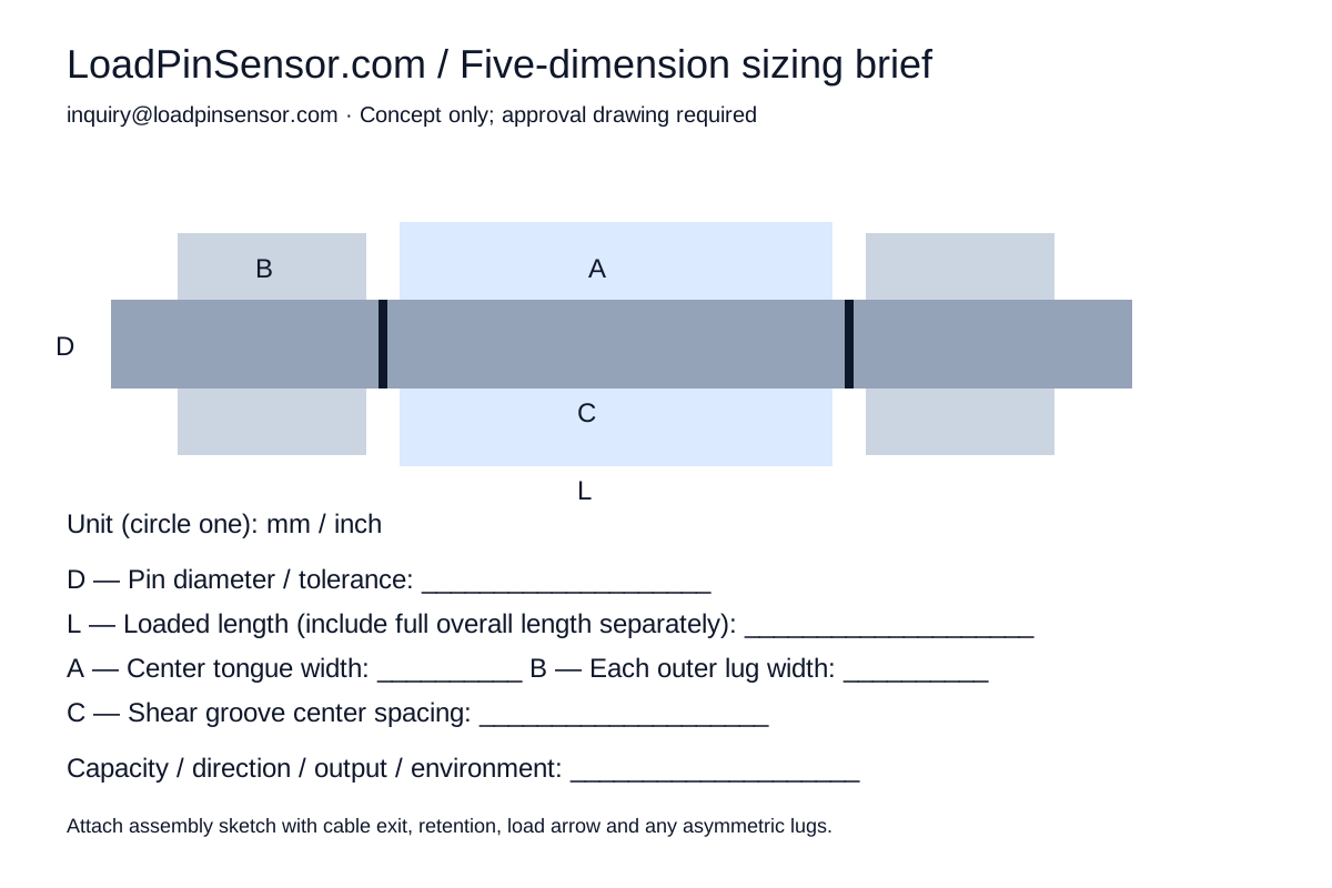
Measure D / L / A / B / C or attach a sketch. We review the joint, load cases and interfaces before releasing a drawing or quotation.
- D
- Pin diameter and fit
- L
- Overall loaded length
- A
- Center loading tongue width
- B
- Each outer clevis lug width
- C
- Shear-groove center spacing
L describes the loaded span here. Include the overall end-to-end length, asymmetric lugs, spacers and retention details in your drawing or notes. Five values start the review; they do not fully define a production pin.
Download sizing sheet ↓